

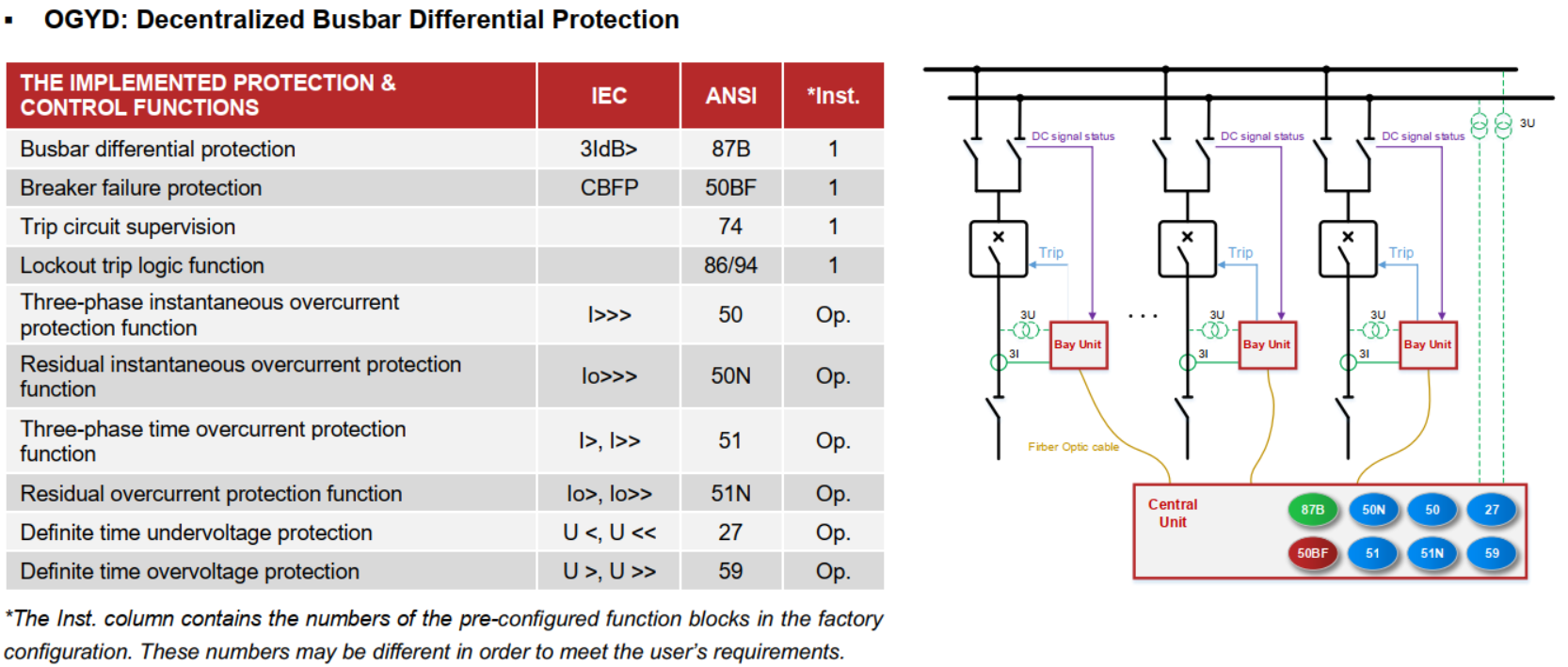
The OGYD product type is designed specifically to be the main unit of a distributed low-impedance busbar protection system to protect bus schemes up to 30 bays.
In this version other individual protective devices of the bays (distance protection, overcurrent protection, etc., or potentially dedicated bay units) are involved in the busbar protection scheme as bay units. Their location in the substation depends on the bay structure of the primary system. These devices perform the sampling of the currents and they have access to all information needed for the busbar protection system. This information is sent by a fiber optic link to the central unit. The calculation and decision are performed by the central unit and the dedicated trip commands are sent back to the devices also via fiber optic links.
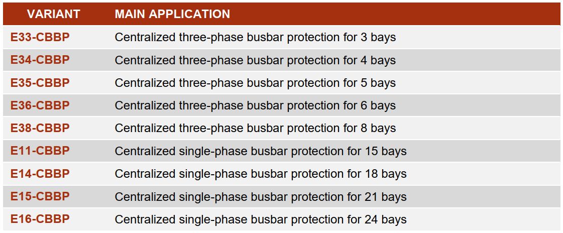
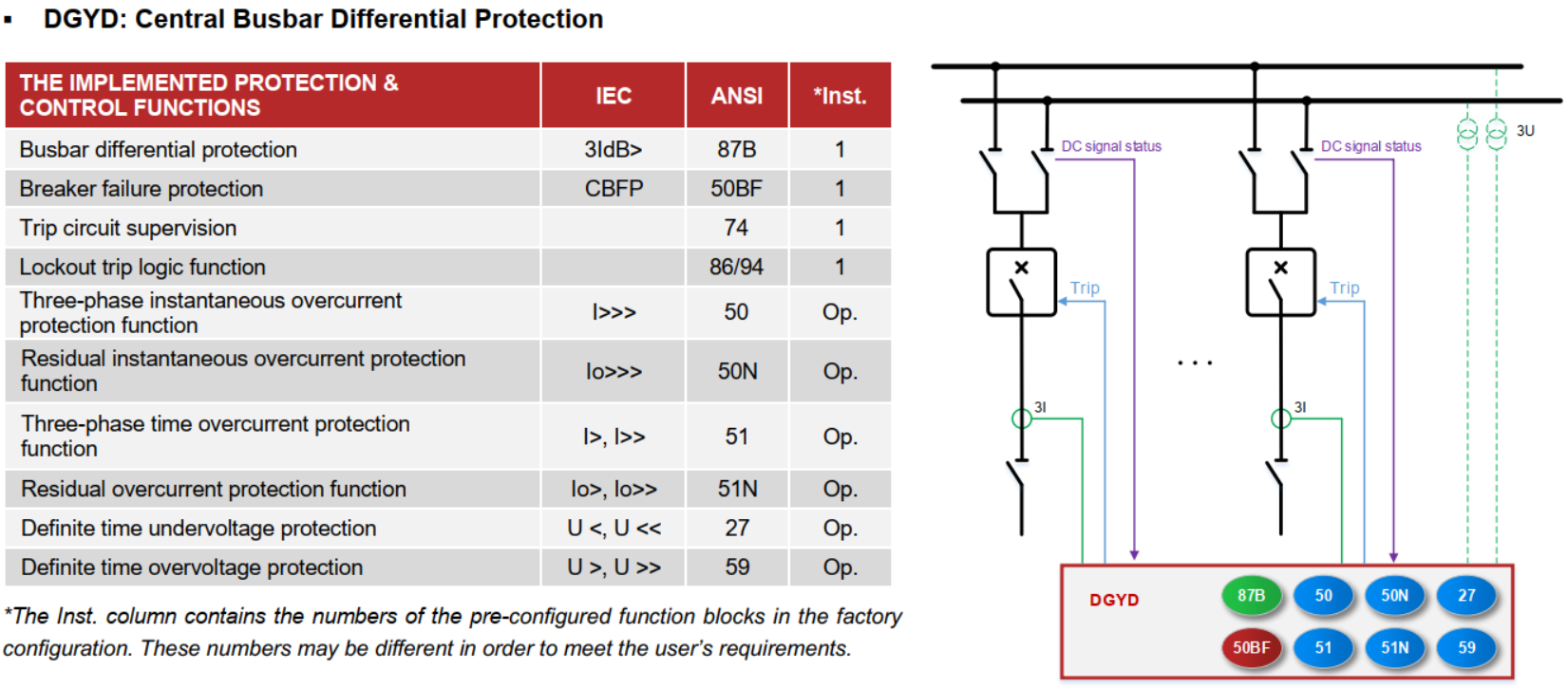
The DGYD type performs fast and stable centralized low-impedance busbar protection in transmission and utility systems, up to 24 bays (for single phase) and up to 8 bays (for 3 three phase).
In this version if the number of bays connected to the busbar is limited (there are a maximum of 8 bays), the tasks related to the three-phase busbar differential protection function are performed within one device. If there are more bays, the tasks are divided among three independent devices. Each of them is responsible for the differential protection of one phase (L1, L2 or L3) of the busbar. The calculation and decision are performed by the central unit and the dedicated trip commands are sent directly to circuit breakers in each bay.
♦ All members of the decentralized OGYD type have the same functionality: the low impedance distributed busbar protection. The difference between them is in the number of the protected sub-units (i.e. the number of the COM modules that communicate with the bay units). The currently available configurations of the OGYD type are listed in the table below (the list may grow over time).
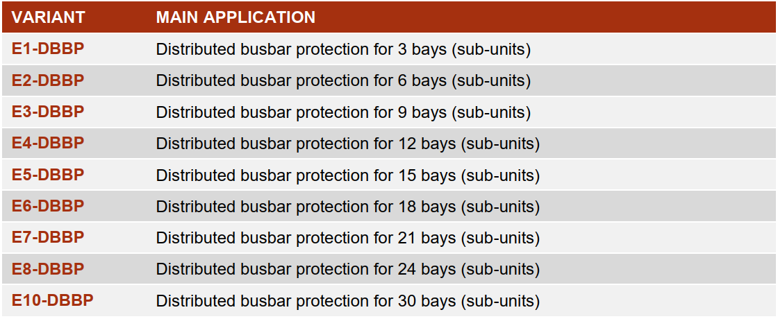
♦ There are two groups of members in the DGYD type, all of them realizing low impedance centralized busbar protection. The first of them handles all three phases of each protected bay (name starting with ‘E3’, see below). The second group has the same functionality, but here one device handles only one phase of each bay (name starting with ‘E1’). This way more bays can be handled with centralized busbar protection function. This also means that to handle all three phases will require three devices. The difference between each member is the number of the handled bays (i.e. the number of the contained CT inputs for the bays). The available configurations of the DGYD type are listed in the table below (the list may grow over time).